ARDUINO VOLTMETER WITH LCD
Apr 1, 2020

In my previous video, I showed you how to build a voltmeter using Arduino, but since the readings were displayed on the Serial Monitor, it wasn’t very portable. Now, let’s take it a step further by displaying the voltage readings on an LCD screen for a more practical and user-friendly experience.
To scale up our voltmeter, we’ll use a voltage divider to safely measure higher voltages. The components required are:
Components Required
- 1 x ARDUINO UNO
- 1 x LCD DISPLAY
- 1 x I²C LCD CONVERTION MODULE
- 1 x 10KΩ Resistor
- 1 x 1KΩ Resistor
- 1 x 10KΩ Trimmer pot (for calibration)
Connections
- Connect the 10KΩ and 1KΩ resistors in series as shown in the diagram.
- Tap the middle connection of the voltage divider and connect it to Analog Pin A0 of the Arduino UNO.
- Upload the code (link in the description) and power up the circuit.
- Apply a voltage to the divider and check the readings.
Calibration & Testing
- I’m using a variable power supply for the demonstration.
- To ensure accurate readings, adjust the trimmer screw until the display shows the correct voltage.
- Important: Make sure the ground of the voltage divider is connected to the Arduino’s ground.
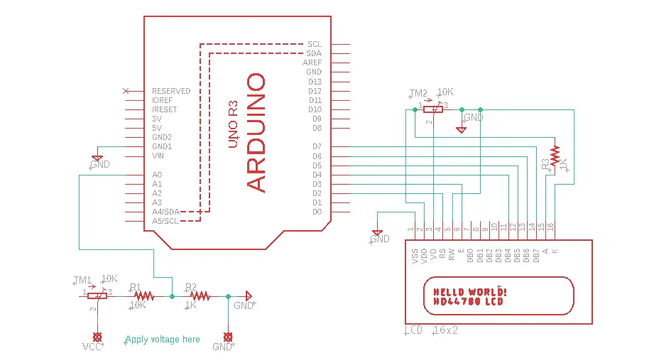
Normal LCD Connections
| ARDUINO PINS | LCD DISPLAY PINS |
|---|---|
| GND | VSS |
| +5V | VDD |
| Center of Pot | VO |
| D2 | RS |
| GND | RW |
| D3 | E |
| NC | D0 |
| NC | D1 |
| NC | D2 |
| NC | D3 |
| D4 | D4 |
| D5 | D5 |
| D6 | D6 |
| D7 | D7 |
| +5V via Resistor | A |
| GND | K |
Circuit Diagram

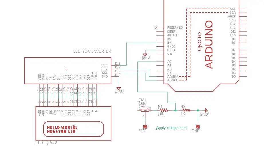
I²C LCD Connections
| ARDUINO PINS | I²C LCD MODULE PINS |
|---|---|
| D4 | SCL |
| D5 | SDA |
| +5V | VCC |
| GND | GND |
Circuit Diagram

Code for this can be found by clicking here
If you like this video hit the SUBSCRIBE button and give a LIKE.