ARDUINO RESISTANCE METER
Apr 11, 2020

In this video, I will show you how to create an Arduino-based ohm meter, also known as a resistance meter. This simple yet effective circuit allows you to measure resistance values accurately using an Arduino and an LCD display. Whether you're a beginner or an electronics enthusiast, this project is a great way to enhance your skills!
Components Required
- 1 x Arduino UNO
- 1 x I2C LCD Display (for easy interfacing)
- Resistors:
- 1 x 1KΩ
- 1 x 2.2KΩ
- 1 x 22KΩ
- 1 x 560KΩ
- 1 x 1MΩ
- Male-to-Male Jumper Wires
- Male-to-Female Jumper Wires
- Push Button (for calibration/reset)
Normal LCD Connections
| ARDUINO PINS | LCD DISPLAY PINS |
|---|---|
| GND | VSS |
| +5V | VDD |
| Center of Pot | VO |
| D2 | RS |
| GND | RW |
| D3 | E |
| NC | D0 |
| NC | D1 |
| NC | D2 |
| NC | D3 |
| D4 | D4 |
| D5 | D5 |
| D6 | D6 |
| D7 | D7 |
| +5V via Resistor | A |
| GND | K |
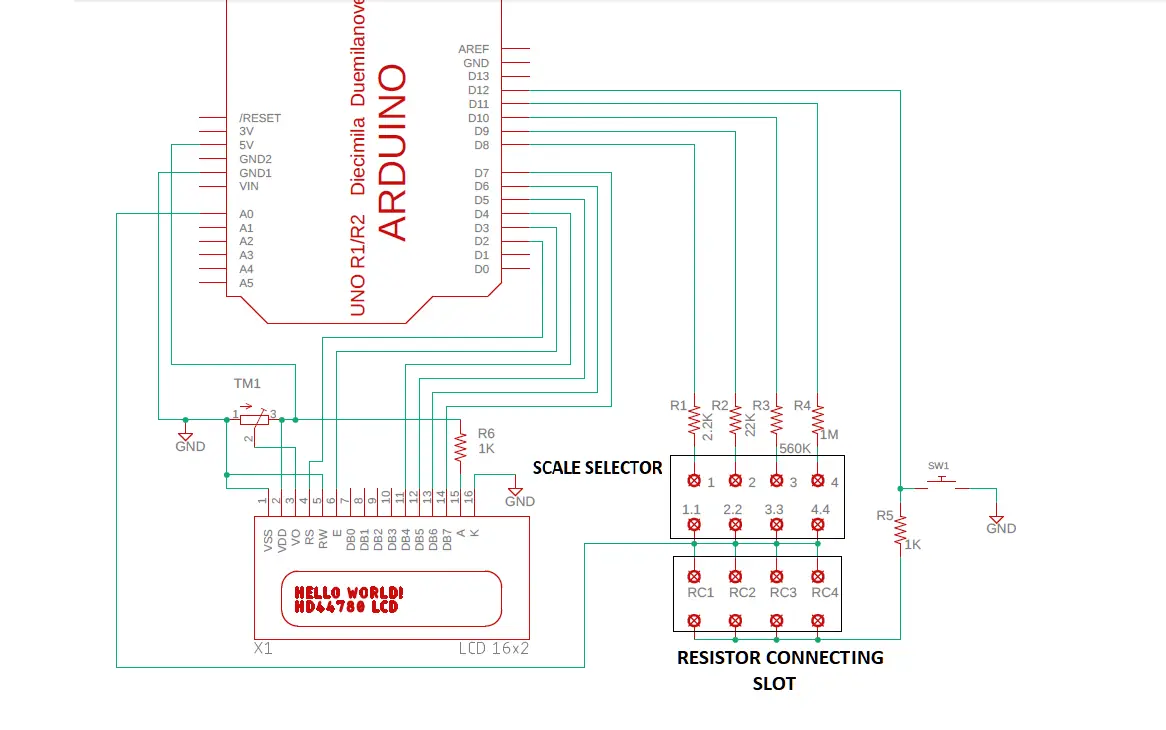
Circuit Diagram

I²C LCD Connections
| ARDUINO PINS | I²C LCD MODULE PINS |
|---|---|
| D4 | SCL |
| D5 | SDA |
| +5V | VCC |
| GND | GND |
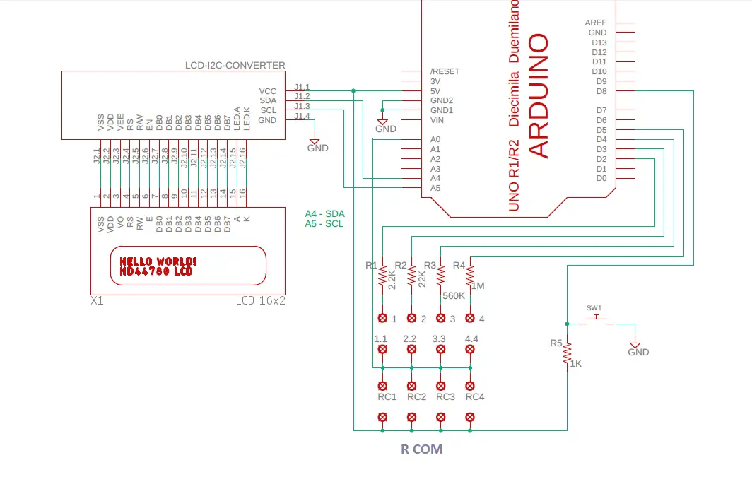
Circuit Diagram

Code for this can be found by clicking here
If you like this video hit the SUBSCRIBE button and give a LIKE.