DIODE OR CONTINUITY TESTER USING ARDUINO
Apr 29, 2020

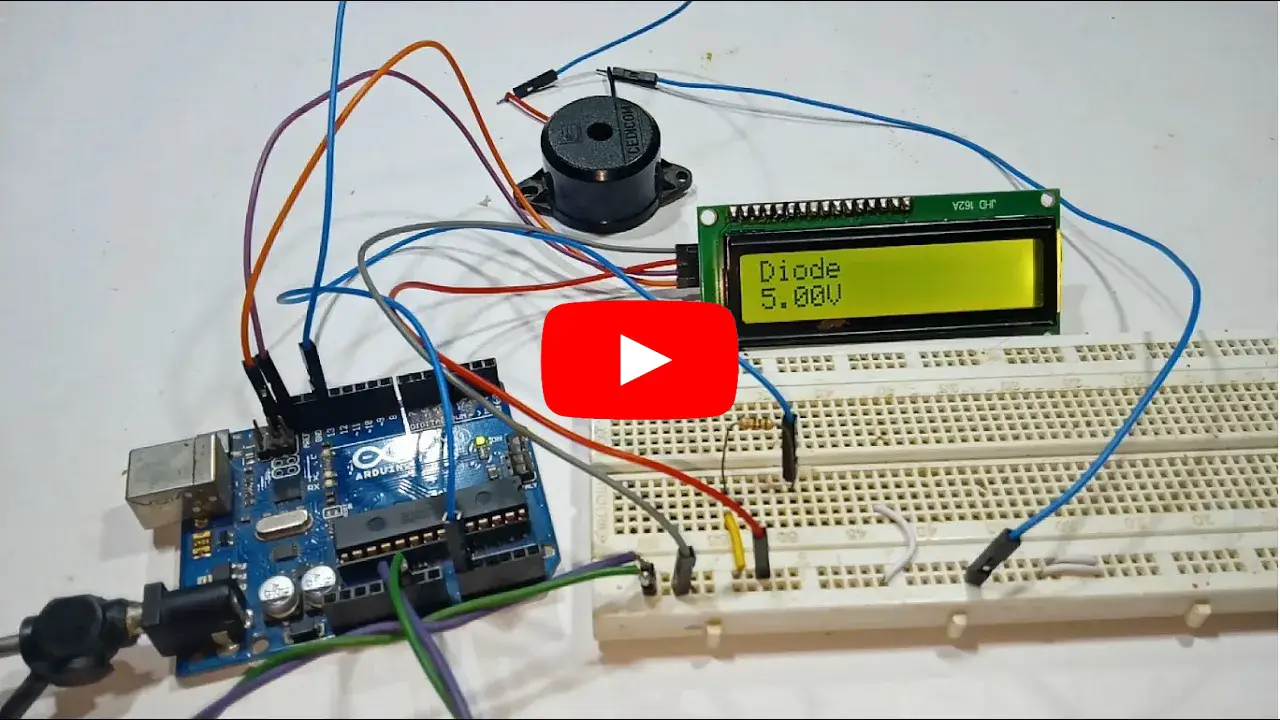
In this video, I'll show you how to build an Arduino-based diode and continuity tester, a handy tool for checking diodes, wires, and circuit connections with ease. This simple project provides a visual indication using an LCD display to show whether a connection is intact or broken.
Components Required
- 1 x Arduino UNO / Nano
- 1 x 1KΩ Resistor
- 1 x LCD Display (Normal LCD or I2C LCD)
- 1 x Connecting Wires
Normal LCD Connections
| ARDUINO PINS | LCD DISPLAY PINS |
|---|---|
| GND | VSS |
| +5V | VDD |
| Center of Pot | VO |
| D2 | RS |
| GND | RW |
| D3 | E |
| NC | D0 |
| NC | D1 |
| NC | D2 |
| NC | D3 |
| D4 | D4 |
| D5 | D5 |
| D6 | D6 |
| D7 | D7 |
| +5V via Resistor | A |
| GND | K |
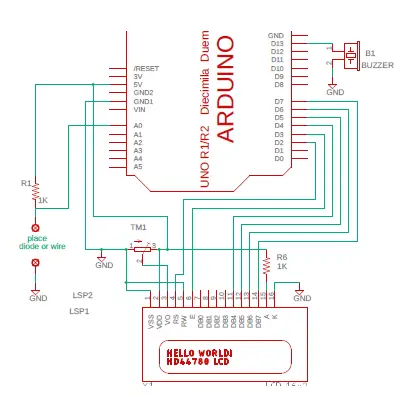
Circuit Diagram

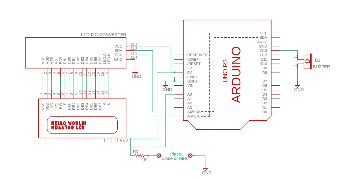
I²C LCD Connections
| ARDUINO PINS | I²C LCD MODULE PINS |
|---|---|
| D4 | SCL |
| D5 | SDA |
| +5V | VCC |
| GND | GND |
Circuit Diagram

Code for this can be found by clicking here
If you like this video hit the SUBSCRIBE button and give a LIKE.